
Control Panels:

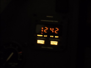
February 18th 2012: The control panel progress is slow but steady. Recently, I have completed the Davtron clocks and they work just as they do in the real word aircraft. GMT, LT, FT and ET. The Flight Time (FT) is the most interesting feature because it is tied to the "weight on wheels" offset within the simulation which triggers a relay on the FDS relay card. When the airplane leaves the ground, the flight time starts and of course stops once the plane lands! I also have wired into the clock harness a ET alarm that will sound off when time counts down.

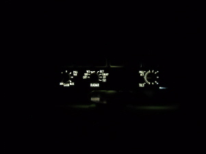
I ordered and received two EFIS panels and a Radar panel from Vince in Italy in kit form. These panels are priceless as far as the amount time that went into the design and workmanship, even in kit form! It took me well over a week to complete them and I still have a little more work to do on them. I worked my own version of back lighting into them in order to match up the lighting with the other panels in my simulator.
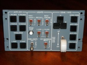
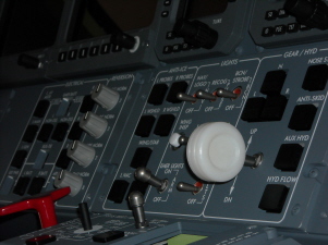
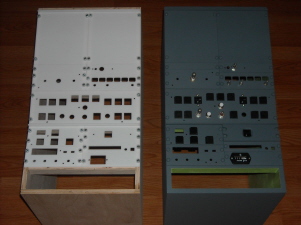
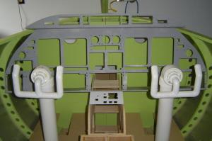
August 25th 2011: (A quick update on the panel building process) I am currently working to complete the lower MIP panels. To date, I have the center panel, electrical panel, left crew lighting panel and the system test panel completed. Notice that the photo above is that of a real Lear45 photo. The two photos below are my simulated panels. Not too bad.
March 17th 2011: It has been a long time coming but I have finally jumped into panel building with both feet! As always, my goal is to make myself some of the best parts / panels possible and then make them available to some of the members of Hangar45.
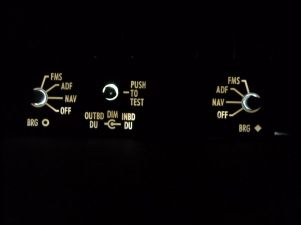
I always imagined that I would start with the Reversion Panels because they are so small. This makes perfect sense starting with these because of the R&D that needed to go into the back lighting work. I decided to deviate from the standard path of back lighting in an effort to simplify the building process. I am using my CNC to cut and back mill the panels and a laser shop for the engraving. Thanks to the late Kris Stow for all his hard work creating the art work files.
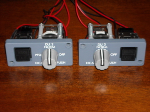
At first attempts at back lighting, you would think placing a few LEDs embedded into the plastic would do the trick, but not so fast.... Hot spots and cold spots show up all over the place. The key is to find a way to spread the light like buttering a piece of bread. The light has to find a way to become even throughout the entire "Light Chamber".
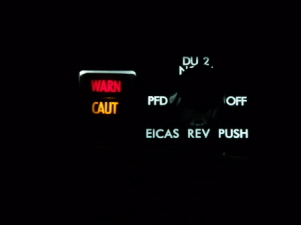
On a side note, because I have sold two Package #3's, I had to work on the development of the double LED/AML issue. Problem solved as you can see from the photo upper right, WARN/CAUT. To learn how to make your own double LED/AML, click HERE
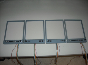
September 24th 2010: I have actually had these for a few months but forgot to share them here. A guy in Italy has a CNC and is a CAD designer. These items are so important, especially in how they are designed because the buttons, rotaries and even the back lighting had to be designed to fit within just the bezel area. The reason for this is because we are using LCD screen to display the function of the instruments which as you can imagine is just right there on the opposite side of the MIP.
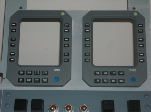

Here are a few pictures of the four Display Units. Notice that the button dividers are 3D?
Backer Panel Starter Kit: For those of you who feel like they have been waiting around forever for someone to develop control panels for your L45 simulator project, this might curb your cravings for a while! I have developed what I call the "Backer Panel Starter Kit". This set of backer panels is designed to get you up and running with some actual hardware in your flight deck! The idea is to get you interfaced with up to 80% of your hardware so that you can move forward with other aspects of your project while at the same time waiting for the front panels to be developed.
All of these backer panels have been designed with the front panels (NOT YET AVAILABLE) in mind so that they will simply set on top of them with no modifications needed. In some cases, like the CDU blanks, they will simply be removed and replaced with a working CDU replica when they are made available. The backer panels have also been designed to use the 389 Replica kit, found on the Hardware and Switches page.
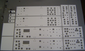
Each kit includes 29 pieces, 1/8th inch thick Acrylic Plastic cut with a precision CNC machine and includes all of the necessary hardware for attachment . For more information and a complete parts list, click HERE. Pictured left is the Backer Panel Starter Kit. Pictured right are two Center Consoles with some of the components from the kits mounted in place.
Project45+Starter+Panel+Backer+Kit
Project45+Starter+Panel+Backer+Kit.pdf
Adobe Acrobat document [56.5 KB]

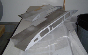
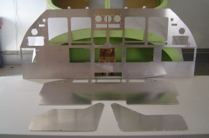
May 14th 2009: I finally found the time to take the aluminum MIP and Glare Shield down to the local metal shop to have it bent in the break. The Glare shield has a .25" radius in the 90 degree bend just under the instrument panel. There is another 18 degree bend that falls about 7.5" back from there.
The MIP has three bends in it. There is a 10 degree bend between the MIP and the top of the lower panels. Then there is a 90 degree bend at the bottom of the lower panels. Last but not least, I added a 30 degree bend to the rear of what I call the "Shin Plate". This will guarantee that there are no sharp edges exposed and it will also help hold any wiring bundles in place. Please keep in mind when looking at the picture to the right that the MIP and Glare Shield are just laying in the shell. It is NOT in it's intended perfect place yet, but it is close!
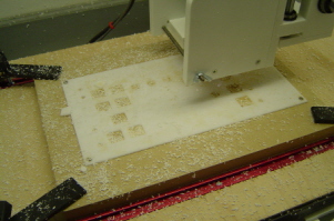
April 10th 2009: I have just finished three solid days of working with the CNC machine and cutting out plastic! The first day I was taken to school by the CNC machine, however, all the lessons the CNC taught me I picked up on quickly. The following two days went much better and I am looking forward to creating more "G" code from the panel files.
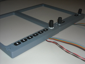
Here you can see all of the Lower Backer Panels, the Engine Backer Panel, the Master Warning Reset Backer Panels and the CDU Blank Panel. You may also notice that I have done all these listed panels in duplicate which is for Eric Tomlin. Also pictured is a spy shot of the AML-21 cap work I am working on. Nothing is as easy as running down to the hardware store and picking up a switch or two. We have to engineer them and then build them! All part of the fun I suppose.
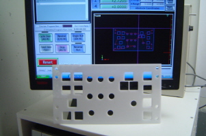
March 21st 2009: On this date, I was officially born into the World of CNC cutting. I cut the Lower Center Backer Panel out
and although I had a few lessons to overcome, this part came out as close to perfect as I could hope for!
The part is drawn out in Auto CAD at 5.25" X 9.4535" and after all the chips settled, the part measured in at 5.25" X 9.4375", basically proving that my machine is very close to being
calibrated. The AML21 switches fit nicely in the .75" square holes you see here. The fit is perfect and snug.
For those of you who are advanced in the art of CNC, I am sorry to bore you with such elementary pictures but I just had to share with the rest of the guys who either just purchased a CNC or are thinking about getting one. I must thank Vince Cimmino in Italy! After all, he is the reason I stepped off the deep end and purchased my own CNC back in October 2008. I think Scott Wegner and Mark Lichtscheidl can say the same. Thanks Vince for being our inspiration!
March 4th 2009: Today, I received the MIP, Glare Shield and the two TQ access doors from Tom Goldburg. The MIP and the Glare shield are the base face plates which all of the main panels will to attach. Pictured right is my father Ron Rollo Sr. opening the package which included the MIP.
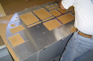
February 25th 2009: I have recently just started working with Tom Goldberg in Washington State who has his own Water Jet cutter. Tom has cut out the MIP and Glare Shield aluminum face plates based on the CAD drawings that Eric Tomlin created. These two aluminum parts will house 75% of the panels. Pictures to come soon.
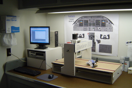
February 18th 2009: I finally got my CNC workshop set up. I have a few more fine, but important details to work out but I had to post this picture for all to see. We are just about ready to start cutting plastic! Thanks to my father, Ron Rollo Sr. for giving up half of one of his work benches for this dedicated CNC space. We have had this work shop for over twenty years and we just brought it out of the stone ages with the internet!
Flight Deck Panels:
There are a total of 39 panels and bezels which include the Pilot and Copilot Circuit Breaker panels, the secondary FMS, optional equipment and the overhead compass. Here is a detailed list of every panel and bezel in the Lear45 flight deck:
Glareshield:
Flight Guidance Controller (FGC) Qty 1
Pilot Display Controllers (EFIS) Qty 2
Reversion / CAUT/WARN Panels Qty 2
MIP Panel:
Display Unit (DU) Bezels Qty 4
Radio Management Units (RMUs) Qty 2
Audio Control Panels Qty 2
Crew Warning Panel (CWP) Qty 1
Standby Instrument Bezels Qty 4
Angle of Attack (AOA) Bezels Qty 2 (Optional Equipment)
Lower Panels:
Hydraulic/Lights Control Panel Qty 1
Pressurization Control Panel Qty 1
Electrical Control Panel Qty 1
Blank Panel (Weight Chart) Qty 1
Pilot’s Crew Lighting Panel Qty 1
Center Pedestal Panels:
System Test/CDR Panel Qty 1
Thrust Level/Flaps/Spoiler Panel Qty 1
Engine/Fuel Control Panel Qty 1
Trim Control Panel Qty 1
HF Control Panel Qty 1
Weather Radar Control Panel Qty 1
APU Control Panel Qty 1 (Optional Equipment)
SELCAL Panel Qty 1 (Optional Equipment)
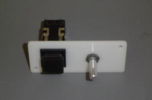
ELT Switch Panel Qty 1 (Optional Equipment)
Flight Hours counter Panel Qty 1 (Optional Equipment)
Circuit Breaker Panels:
Pilot's Circuit Breaker Panel Qty 1
Copilot's Circuit Breaker Panel Qty 1
Please feel free to contact me via my email at ronjonrollo@yahoo.com for more information on any of these panels.
Contact Us Today!
Email:
Please visit Hangar45 for all the latest news in the Lear45 simulation world. There you can meet with all the L45 builders and watch their projects unfold!

Project45 Products and Pricing Page coming soon!
"In the meantime, please email me for the latest Project45 Products and Pricing Guide and I will get a PDF copy out to you ASAP!"