
My Project45:
December 2004: I had an idea!...
Who wakes up out of the blue and says, “I think I’m going to build a full scale flight simulator!” No one does. It comes from a deep rooted seed that was planted years and years ago.
Ever since I could remember, I have loved everything about aviation. As a kid, I marveling at the A-6 Blue Angles and their precision flying formations during air shows. Between that and listening to my Uncle Wayne tell stories about his WWII aviation adventures, (who by the way flew everything from a DC-3 to the Concorde), lead me to spend 10 years in the U.S.N.R. on the P3-C Orion as an Acoustic Sensor operator.
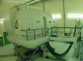
During my time in the Navy through the 90’s, I had the opportunity to fly the P3 simulators here at NAS Jacksonville Florida on a couple occasions. Even though it was 70’s technology, I was completely sold and blown away with the realism of the flight simulation it created. There was hardly a difference from what I knew about real flight and the artificial flight that these simulators produced. I had to have one, but couldn’t afford the $15,000,000 price tag!

Just a month prior in December 2003, my wife Michelle made the simple mistake of getting me a relatively inexpensive “video game” called, FS2004 for Christmas. I have had most of the Microsoft flight simulators prior, but this one seemed to take a huge leap forward, particularly with it's graphics compared to the previous versions. Between this and people sharing information on this growing subject on the internet, it was clear to me that a home built flight simulator could be achieved for under $25,000.
March 2004: Selecting an aircraft...
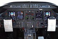
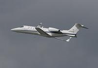
The next step was choosing an aircraft to model. I naturally thought of the Orion P3-C, the Boeing 737, the 747 and several other aircraft which all have their own benefits, however, they were physically too big for the space I had to work with at the time. I ended up selecting the Bombardier Learjet model 45 XR because it’s smaller, not as complicated to build as some of the other favorites, and still required two pilots to fly, “legally”. This jet also has a decent range with modern avionics, not to mention it looks cool. Another nice attribute with this smaller aircraft is it will allow me to be able to fly into thousands more airports compared to the larger choices. For more information on Lear45, click HERE

April 2004: Setting a few goals...
After I finally selected an aircraft, I set one simple general rule to follow:
Rule #1: DO NOT USE AUTHENTIC AIRCRAFT PARTS!
(But I guess rules are made to be broken because I have acquired a few real parts!)
It’s an easy rule to follow because generally, I can’t afford the real parts anyway. I also want to be able to build the majority of the components myself and take pride in the fact that I built this simulator literally from the ground up. Unlike other aircraft like the Boeing 737 and the Airbus A320, there are no commercial vendors to turn to for parts! They will have to be built either by myself or friends who share the same dream.
I have set a goal to have the project flyable after five years from the time that I actually start building it and fully completed after ten years. (For the record, I started construction of the PROJECT45 in January 2008.) To most people, this sounds like an outrageous goal but trust me, the vision in the end will pay off ten times over! During this time period, my time will also be split helping others with their L45 projects as well.
I set a goal to build the simulator to be at least 95% functional and be completely enclosed to enhance the effect of immersion. This is where the term “Flight Simmersion” comes from. The outside environmental view will be 220 degrees of panoramic view on a curved six foot radius seamless screen stretching 24 feet long and six foot tall. I will use three short throw projectors, a TH2GO unit and Nthusium software to warp the projected images onto the curved screen. You will have to see this to believe it!
Another goal that I have set for myself is that I wanted to build the simulator strong enough to be mounted on a motion base platform with three degrees of freedom (D.O.F.), Pitch, Roll and Vertical (Heave), which I believe are the three most important of the six axis and easiest to achieve. In case you are new to this hobby, the other three are Longitudinal (Thrust), Lateral (Sway) and Yaw. I have put much thought into the possibility of using a motion base platform and will more than likely NOT build one for several reasons. First, the cost can run anywhere from $5,000 to $50,000 just for the motion systems. Second, lack of vertical space. And third, I am modeling a Lear45 which is a corporate/business jet. It is the pilot's job to keep the aircraft as smooth and steady as possible for the passengers. Therefor, why completely blow the budget for 2 minutes of thrust and a few seconds of deceleration?
However, if funds and space were not an issue, the platform would have up to 15 degrees of motion in any direction, which means the angle could change by as much as 30 degrees from one max stop position to the opposite extreme. This would be more than enough movement to play tricks on your equilibrium along with what your eyes are telling you. It is surely possible but certainly not needed. In any case, the simulator WILL be constructed strong enough to accept the forces of the motion system.
May 2004: Plans and Drawings…
I started sketching and drawing in April 2004. My first drawings were very crude to say the least. During the first four years, my drawings have honed into something that I now feel comfortable with building and putting the effort into. I try to think of everything when I am working on a draft, things that most people would never give a second thought to. All the extra attention to detail will pay off near the end of completion.

January 2005: The Flight Box…
In between drawing, I needed to convince myself that I could in fact build (in my opinion) one of the most complicated projects a guy could undertake in his garage. I spent about $1,000 and 8 months of time building what I call my “Flight Box”.
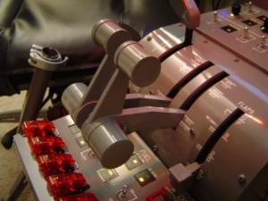
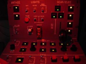
The most important feature is the throttle quadrant “TQ”, which is actually a CH Throttle Quadrant that I modified to fit and work as I needed it to in this project. It also has most of the major functions that the L45 has, including the Engine Panel, Auto Pilot, Anti Ice and the Gear/Elec Panel. I even included the major failures that could happen in flight.
I built my own panels using Plexiglas, aluminum sheeting and K-1 switches from Flight Deck Solutions. I used an input card from Beta Innovations Inc. to link the Flight box to my computer. Over all, it was not so tough but I had to be focused, orderly and dedicated to the project to get everything dialed in just right. The Flight Box has worked flawlessly for over several years with no issues!
January 2006: Temporary Desk Top Simulator…
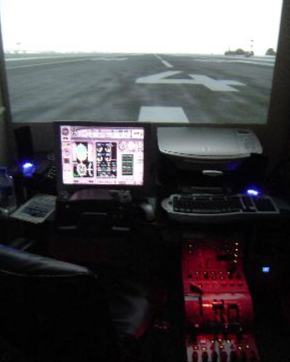
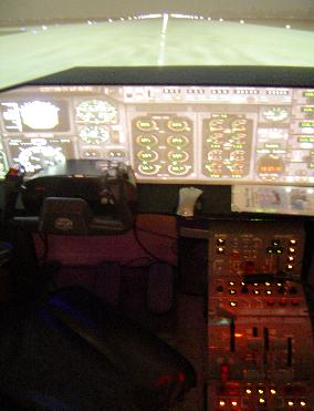
Using my Flight Box, a 20” LCD screen, an over head projector, CH Yokes, CH Pedals and a Butt Kicker system, I created a temporary flight simulator that did not take up much space in the bedroom. I split the video feed so that the outside view was on the wall via the projector and my instruments were on the LCD screen.
I started fooling around and built a temporary glare shield out of poster board to split the projector image to create a full scale virtual cockpit of a 737NG! Cool, but I still needed to build my ultimate vision.
October 2007: Shell Drawings…
I finally got all of my “other around the house” projects completed and out of the way, including restoring my 1981 Chevrolet Corvette. Now I could concentrate on what I have been dreaming of! In my spare time, I sketched ideas and refined them several times over. I also built a full scale frame section to get an idea of how the materials were going to work together. You would not believe the strength that this model has!
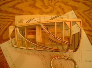
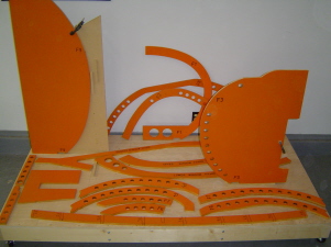
November 2007: 1/12th scale model...
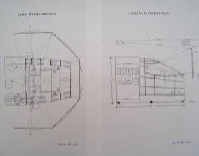
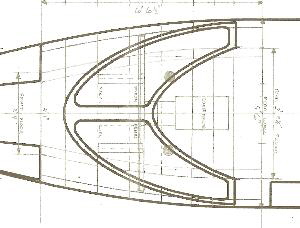
Once I decided to move forward with building a full scale flight simulator, one of the biggest challenges was creating the shell to look like an actual L45 nose section AND at the correct scale. The dimensions inside and out had to be almost perfect to accommodate the MIP, yokes, pedal assemblies, center pedestal, glare shield, circuit breaker panels, seats etc. It took several weeks of fine tuning my numbers and measurements before I was comfortable with my plans. As a matter of fact, I started another model before I realized that the measurements were off. That one got scrapped!
I used a three drawing picture and a few known measurements to build my 1/12th scale port side model. I only needed one side because the parts could be flipped over to duplicate the starboard side. The other reason for modeling just the one side was to make sure both sides were identical, imperfections and all. Some folks might say, “Why not use a CAD program to draw out the design of the shell frame?” Truth be told, at the time I had zero experience with CAD. (These days I draw nearly everything in CAD)

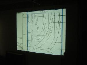
December 2007: Transition the plans to full scale…
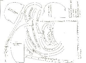
As I was building the model, I traced each part onto half inch grid paper. I scanned the drawing into my computer and blew the image up to full scale on three foot wide paper that I had hanging on the wall using a projector. The grid system that was previously a half inch was now six inches. Then I traced the images which gave me a rough idea of the full size scale of the shell. It didn’t take me long to see that this method was only going to get me close because there was about 3/8 inch distortion in some places on the six inch grid system. Keep in mind that if you are just a fraction off on the model, that fraction turns into inches!
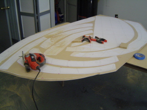
January 2008: Port side full scale “Jigs” (L45-001)…
In January 2008, I officially started construction of the PROJECT45 now that I had a rough full scale shell on paper. I decided to use Medium Fiber Density Board (MDF) because it was cheap and I was going to be making a lot of mistakes. I started at the rear wall and then worked my way up to the center line. I then worked on the overhead jigs which weren’t too bad. Then I rough cut each frame section and used a lot of “line integration” to get everything as close to perfect as the naked eye could get it. It took several weeks to get things to a point that I was happy.
From this point one, I was ready to start constructing my Shell frame, L45-002.
Please go to the L45 Shell page to see more information on the shell construction, the finished product and a list of shell owners around the world!

Contact Us Today!
Email:
Please visit Hangar45 for all the latest news in the Lear45 simulation world. There you can meet with all the L45 builders and watch their projects unfold!

Project45 Products and Pricing Page coming soon!
"In the meantime, please email me for the latest Project45 Products and Pricing Guide and I will get a PDF copy out to you ASAP!"