
Flight Controls:
This page covers the physical "Flight Controls" of the L45 simulator but is not limited to just the Control Yokes, Rudder Pedals and Engine Throttles. This page will also be covering the Spoiler Arm, Flaps Lever, Emergency/Parking brake, Emergency Gear Free fall Handle, pitch disconnect handle, Throttle Quadrant Pedestal, Center Pedestal, MIP stand support and the Glare shield structure.
May 15th 2014: Greg Branch came down from Savannah Georgia and we knocked out the roll connection between the pilot and first officer's yokes with aluminum 1/16th inch cable. This was a big deal and a long awaited item for myself and many others that were waiting to see how this would turn out. I can not express how happy I am with the way it turned out! The roll is very smooth, tight and has no play between the two yokes. I was also able to get them to snap back to center for both roll and pitch! Later on I may look into adding feedback and autopilot movements with servos or stepper motors, but not until higher priority items are addressed first.
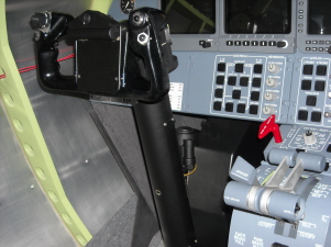
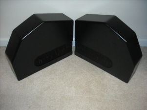
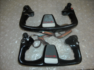
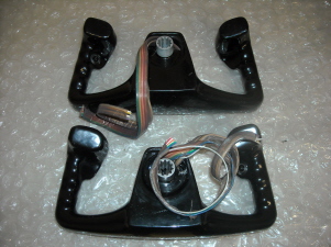
September 7th 2013: Several months ago I designed and completed the column covers that fit over top of the column heads. They are made from plug and molds. Each piece has three pieces of fiberglass in it and are sanded into shape with an orbital sander, in other words, lost of hard work and time. In addition to that, I had both of my yokes stripped and powder coated. While I was at it, I rewired my yokes so that they would work flawlessly with the Flight Deck Solution interface cards. Take a look at these photos!
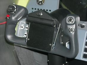
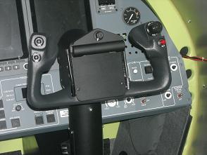
August 2nd 2012: It has been a year since I have updated this page but not because I have not been making progress. But now I am finally at a point where I can post some nice detailed photos of the new control columns and column heads. I also took this opportunity to modify and attached the stick shakers to the columns. For more information on the control columns and column heads, please visit Hangar45 a read through the Project45 Control Column Kit thread HERE

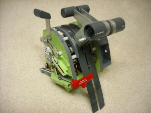
August 26th 2011: I have actually had the TQ module completed for several months as seen in other threads and post but have not had it posted here. The final product is a module that can be removed all in one piece for easy repair or updates. It has one Leo Bodnar BU0836X interface card mounted to the bottom of it for easy removal by unplugging only one USB! Every function works like the real L45 with the exception of one feature, although in the future I plan to implement it as well. There are two solenoids that lock out the reverse thrust levers while the aircraft is in flight and there is NO weight on the wheels. It will be a fun project in the future!

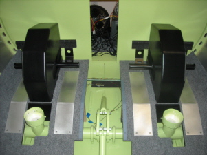
Here are a few photos of the pedal assembles with more of the surrounding hardware in place. In the next few months, I hope to get back to work on the final steps to completing the control columns, control column heads and yokes.
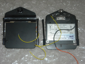
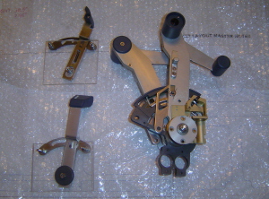
September 22nd 2010: I was lucky enough to acquire a set of chart holders from Rand Mathews, one of our Hangar45 members. These chart holders are going to work perfectly in my project. As a matter of fact, they are also going to save me weeks worth of work because now I do not need to modify my L35 yokes to give them the L45 look.
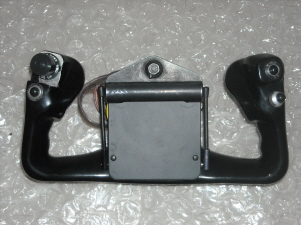
My rudder pedals and rudder pedal covers are complete. The covers by themselves took almost a month to finish. I have completed a tutorial and have it posted over at Hangar45. You can check it out by clicking HERE Here are a few pictures of the completed rudder pedal assemblies with the covers installed.
June 22nd 2010: Work and modifications to the rudder pedal system is just about complete. I am currently working on mounting the set into the flight deck. As you may have read either here or in Hangar45, Tom Goldberg worked very hard on the design of these interlinked rudder pedals. I have to thank Tom for his work in this part of the L45 project! To read more about the evolution of the rudder pedals, go to the Hangar45 thread HERE

A few months back Shane Barnes was able to get me a matching set of Lear35 yokes for my L45 project. I will have to do some work to them in order to give them more of a L45 look. This will include reworking the switch bezels so that the engraving and lettering will be up to date, painting the yokes with a textured flat black paint and finding a chart holder. The center cap area is also much different but I am still debating if I am going to rework this area because of the fact that it will be hidden by the chart holder. I may have to do some rewiring too but we will see when that time comes.
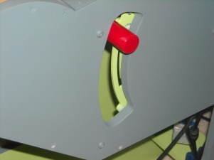
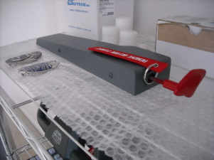
I have also recently completed the Emergency Landing Gear Free Fall Handle. I did not have much information to work off of but I did have at least one picture that gave me enough clues as to what was going on with it. The main thing about this lever is that it has a "gate" similar to the flaps and spoilers. This gate locks the handle in the up position and also in the down position. This is another one of those little "wow' factors in the simulator because 99.9% of the time, it will never be used. But, it is cool knowing it is there AND it does work in the event the main gear toggle fails! To read more about the Emergency Landing Gear Free Fall Handle, click HERE.
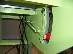
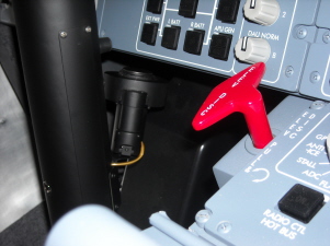
April 21st 2010: The TQ module has been front and center for the past month. To date, I have designed and built two sets for other builders, now it is time to complete my own. The design is simple to a point. There are two main wooden structures that the throttles are attached to. Then on the outside of that, the Flaps, Spoilers and Parking Brake are attached. I am using slider pots to gauge the position of each of the levers which of course that signal is sent to an I/O card and then to the computer. As you may know, I am using authentic parts which turns out to be the best solution because most of the mechanical functions are already built into the parts!
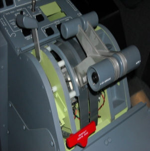
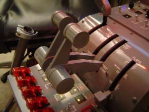
The throttles have the detents built in to them including CUT OFF and APR which requires the side latches to be pulled up in order for the throttles to be placed in these positions. The thrust reversers work but are locked if the throttles are in the CUT OFF position. The MUTE and GO AROUND buttons are also included in the real throttle levers but need to be wired.
The flaps and the spoilers have detents for each of the positions that they could be in and are also spring loaded which locks the levers into that spot until they are pulled out and moved. All these functions are great because it gives me a head start in making the TQ module.
Here are some pictures of the TQ module to date:

Notice the clevis and rod that is attached to the levers and then to the pot. You can also see the switch that tells the I/O card that the throttles are in the CUT OFF position.
All of the mechanical issues have been worked out. Next I will work on some of the cosmetic items such as the Flaps bucket, throttle slider covers, the curved aluminum TQ backer cover plate and hold down bracket. The last item will be the curved TQ plate which will be engraved and back lit!
January 15th 2010: I have been slowly working on the flight controls and the MIP. A guy in Italy has been working on my DU's and RMU's. As soon as they arrive here in the U.S.A. I will be able to finish the MIP enough to mount it onto the MIP Tower.
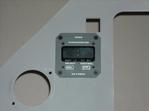
Some of the smaller details that I have been working on are an authentic set of Davtron M850 clocks and a custom made Pitch Disconnect Handle made by Shane Barnes. I made the Pitch disconnect box out of MDF, Bondo and lots of primer!
June 24th 2009: I have been working on developing the MIP Backer Support and MIP Tower. So far it is coming together as planned. Here are a few tips to keep in mind when you are building your big hardware or "furniture" items:
1. Have a GREAT idea of the overall project. It's not something that you just throw together over a couple of weekends. It requires a lot of planning and thorough thought of all the components involved.
2. Use the drawings on the resources page in Hangar45 This will save you hundreds of hours of research, planning, scaling and development. The hard part is already done!
3. Build your unit from the ground up. Your can't work on the glare shield until the MIP is done, and you can't work on the MIP until the TQ is done!
4. Build your interior furniture pieces so that it is modular, meaning you can easily take it apart to move it from one place to another or work on a particular component or system.
5. You can order the aluminum MIP and Glare shield from Project45 by contacting myself at ronjonrollo@yahoo.com These aluminum parts are worth every penny and a must for the build!
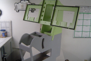

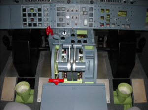
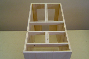
This is the MIP backer support structure standing alone, (left). Here you can see the MIP backer support married up to the TQ WITHOUT the aluminum MIP in front of it, (right). Notice how the Aluminum MIP lays perfectly flat on the MIP support. I have 1/8th inch foam strips between the two for sound dampening. This will keep the rattles down!
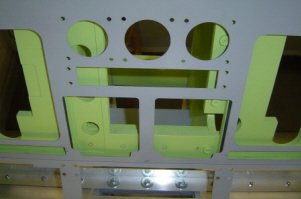
You can see the 1.5" aluminum "L" beam that I have attach to back side of the "shin Plate" which is behind the lower panels. The three LCD screens will fit perfectly between the aluminum MIP and the MIP backer support like a sandwich.
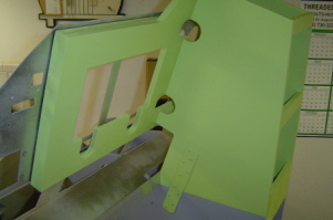
The aluminum MIP, believe it or not, is only going to be held in place with three bolts, (seen here lower left). The aluminum MIP rest firmly against the MIP structure and is surprisingly tight and secure. We don't want to ruin the look of the L45 MIP with a bunch of screws in places that they don't belong! The Glare shield above, (not pictured yet) will also aid in holding the MIP in place.
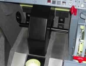
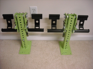
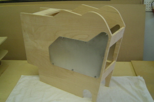
March 13th 2009: I just finished the main parts to the Center pedestal. It may look a little on the complex side, but in fact, I am trying to keep it simple! I used two pieces of .5" X 1" Birch to make the rail system. All the control panels will have a .5" mounting surface. Also notice where the Center Pedestal is going to set on top of the raised floor under the seats. The notch at the bottom of the CP also acts as a "LOCK" and keeps it in place. There will also be two bolts holding the TQ and the CP together.

March 11th 2009: Here are a few pictures of the Throttle Quadrant Pedestal, (or as we call it, furniture), in the early stages. A lot of time and effort has gone into this design to insure that this part is going to mesh properly with all the major components of the simulator. In a sense, the TQ brings everything together! If you study these pictures closely, you will see where the Control Column Crossover arm will fall, the Dual Rudder Control Pedal cut out is, the lower panels and MIP platform will rest, and of course the Throttle Levers themselves.

January 23rd 2009: I have been working on developing a control column system inside the flight deck. To date, I have most of the components in place and it works very well. It actually runs across the top of the sub floor but under the raised floor sections.
November 25th 2008: I was very fortunate to acquire an authentic set of Throttle Levers along with the Flaps and Spoiler levers! This is going to save me countless hours attempting to replicate the many actions that these parts are tasked with. Not to mention that the look and feel can not get any more real than the real thing!
Currently, (until my full scale simulator is operational), I am using a modified CH Throttle Quadrant that is built into my "Flight Box". I cut off throttle levers #2 and #5. I use #1 for the Spoiler ARM, #3 for engine #1, #4 for engine #2 and #6 for the Flaps lever. At the time, I found this to be a fairly easy way to replicate the main functions of the throttle quadrant in the L45.

Contact Us Today!
Email:
Please visit Hangar45 for all the latest news in the Lear45 simulation world. There you can meet with all the L45 builders and watch their projects unfold!

Project45 Products and Pricing Page coming soon!
"In the meantime, please email me for the latest Project45 Products and Pricing Guide and I will get a PDF copy out to you ASAP!"