
Interfacing:
This page is dedicated to interfacing and hardware logic.
FDS SYS4X High Capacity Interface Card:
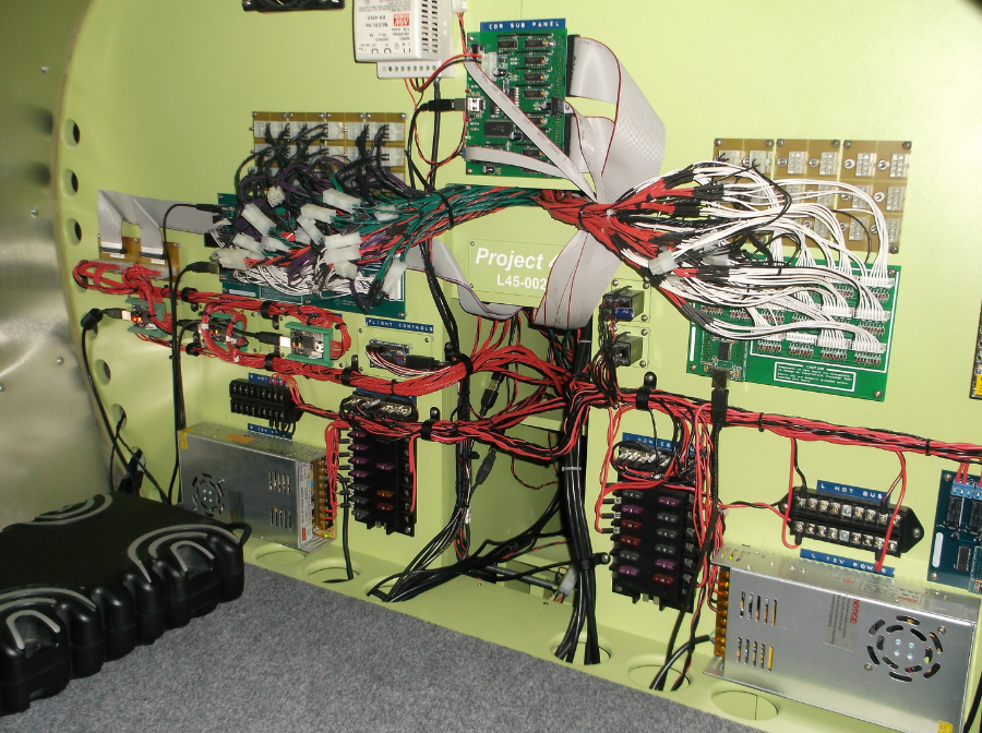
The FDS SYS4X System Interface Card is my main interface card that will handle 64inputs (switch functions) and 128outputs (LED indicators). FDS makes this card and related software super easy to work with. Basically, I can wire up everything to this board and then later on assign each switch or LED it's specific function using the software. Among all of the features this card has, it also includes software logic for things like the landing gear indicators and lighting system checks. For the switches that have no offsets in MS Flight simulator, I can create enough software logic to give even the "dummies" perceived life! For more information on this board and others that FDS offers, click HERE
To make the wiring process a little neater, I designed grounding terminals pictured above the FDS board. Eight grounds will plug into each isolation block and one ground line will come out and connect tot he SYS4X board. This will allow me to wire every switch and LED and send the wires into the Avionics bay to be sorted out there. It will also result in a cleaner wiring process.
FDS-SYS2X High Capacity Interface Card:
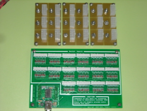
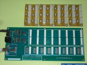
The FDS-SYS2X Interface Card will handle up to 128input switching functions. FDS makes this card and related software super easy to work with. I can wire up everything to this board and then later on assign each switch it's specific function. For the switches that have no offsets in MS Flight simulator, I can create enough software logic to give even the "dummies" perceive life! For more information on this board and others that FDS offers, click HERE
To make the wiring process a little neater, I designed grounding terminals pictured above the FDS board. Eight grounds will plug into each isolation block and one ground line will come out and connect tot he SYS2X board. This will allow me to wire every switch and LED and send the wires into the Avionics bay to be sorted out there. It will also result in a cleaner wiring process.
FDS-SYS-R1X Relay Board:
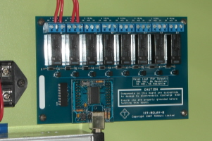
The FDS-SYS-R1X Relay Board is the piece of hardware that will really allow me to create a flight deck that functions like the real thing. It will act as a second layer of hardware switching, however, it will be controlled by the Flight Simulator software along with the Jet45 AAS software. The card has eight relay channels that either cut power or connect power using software offsets. Pictured above I already have the left electrical bus and the right electrical bus wired into two separate relays. In the future, the software will tell the relays to either apply or cut power to these buses which in turn will apply or cut power to several components on those buses. Some of the other components that this card will help operate are the Hobbs Hour meter, stall stick shakers, Davtron Clocks, APU, reverse thrust lockout solenoids, etc. For more information on this card and others that FDS offers, click HERE
Pokeys56U Cards:
The Pokeys56U cards are great for encoder programming and basic switch functions that do not require indepth software logic. Pictured below are three Pokeys56U cards that control the four display units and the two Radio Management Units otherwise known as the RMUs. More infor soon!

Leo Bodnar BU0836X:
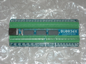
The Leo Bodnar BU0836X Boards are the first interface cards to make their way into my PROJECT45 primarily because of their ability to handle potentiometers. Each one of these BU0836X boards has the capability to handle eight POTs, one eight position hat switch and thirty two (32) ON/Off switches. These two boards will be responsible for all of the flight controls including ROLL, PITCH, YAW, Throttles one and two, Flaps, Spoilers, Pilot's left and right toe brakes and the Copilot's left and right toe brakes. In addition to this major controls, they will also handle Fuel Cut Off, Thrust Reversers, Parking Brake and many other misc functions.
There are two features that make these boards a MUST have! First, the easy connect and disconnect buttons for your wires. Other boards require you to solder the wires to the leads on the boards. There is plenty to solder with this project without creating twice as much work for myself. And, if I need to remove a function, it is as easy as pressing a few small buttons!
The other feature that I like about this board is the fact that every input has it's own ground and positive input terminal. Some other boards operate with what is called an "Input Matrix". An Input Matrix is a system that only has a limited amount of terminals. It works with the use of rows, columns and shared grounds. The end results is that the Matrix boards work fine, but it can be more than a little confusing getting them set up right being that the functions share terminals and grounds!
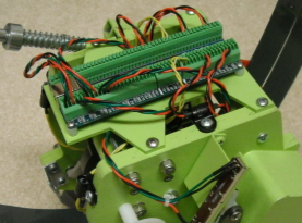
Pictured above right is one of the Bodnar boards attached to the bottom side of the TQ module. I designed the TQ module so that in the event that I needed to pull it out for maintenance, only one USB plug would need to be unplugged to remove the module. As you can see, I have plenty of spare inputs left over on this board which will probably never be used, other wise, it defeats the purpose of making it easy to remove!

Contact Us Today!
Email:
Please visit Hangar45 for all the latest news in the Lear45 simulation world. There you can meet with all the L45 builders and watch their projects unfold!

Project45 Products and Pricing Page coming soon!
"In the meantime, please email me for the latest Project45 Products and Pricing Guide and I will get a PDF copy out to you ASAP!"